Master FreeCAD CAM: A Step-by-Step Guide to CNC CAM Modeling
This article provides an in-depth exploration of CNC CAM modeling, covering foundational concepts, practical applications, and engineering insights.
Transforming a digital 3D model into a physical part is one of the most rewarding aspects of digital fabrication. However, bringing your design to life on a CNC machine requires powerful toolpath generation tools. Mastering CNC CAM modeling is the essential skill that allows makers, engineers, and hobbyists to convert 3D geometry into precise G-code instructions.
While proprietary software often comes with steep subscription fees, FreeCAD offers a robust, open-source solution through its built-in Path (CAM) Workbench. Here is how you can leverage FreeCAD to streamline your toolpath generation and take your manufacturing projects to the next level.
Why Choose FreeCAD for CAM Workflows?
FreeCAD has evolved significantly, offering a feature-rich environment for computer-aided manufacturing. Its integrated workbench allows you to work directly on your parametric 3D models without needing to export files between different software platforms. From simple 2D profiling to complex 3D pocketing, FreeCAD provides precise control over feeds, speeds, cut depths, and entry strategies.
Core Steps in the CNC CAM Modeling Process
Streamlining your CNC CAM modeling workflow in FreeCAD requires a methodical approach to ensure accuracy and machine safety:
- Job Setup: Define the stock material dimensions and establish the machine work coordinate system (WCS) origin relative to your 3D model.
- Tool Controller Configuration: Input cutting tool specifications—such as end mill diameter, flute length, spindle speed, and feed rates—tailored to your specific stock material.
- Operation Definition: Apply specific toolpath operations, such as Profiling (cutting outlines), Pocketing (clearing enclosed areas), or Drilling.
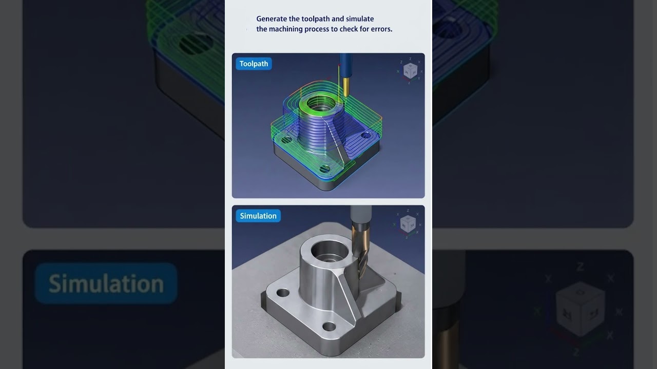
- Toolpath Simulation: Utilize built-in visual simulations to inspect cutter motion, verify material removal, and check for potential collisions before sending instructions to your machine.
Exporting G-Code for Production
Once your operations are finalized and verified, the final step is post-processing. FreeCAD supports a wide range of post-processors tailored to popular controllers, including GRBL, Mach3, and LinuxCNC. Post-processing translates your visual operations into clean G-code ready for your controller.
By refining your CNC CAM modeling techniques in FreeCAD, you can achieve full control over your CNC router or mill without relying on expensive software subscriptions.

No comments:
Post a Comment