Demystifying CAD/CAM: How G-code Drives Modern CNC Machining
This article provides an in-depth exploration of G-code, covering foundational concepts, practical applications, and engineering insights.
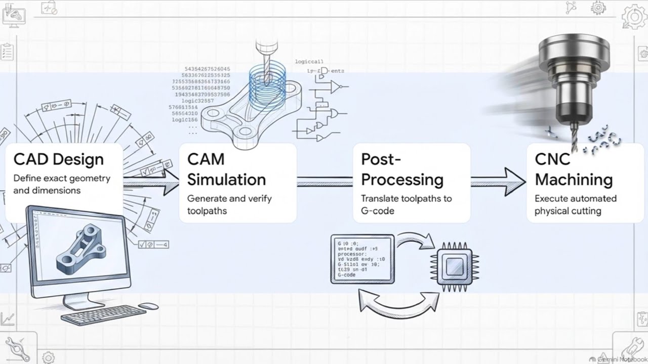
Modern manufacturing relies heavily on the seamless integration of Computer-Aided Design (CAD) and Computer-Aided Manufacturing (CAM). From conceptualizing a part in software like SolidWorks to cutting metal on a CNC mill, understanding this digital pipeline is essential for engineers, machinists, and makers alike. Here is a step-by-step breakdown of how CAD/CAM works to bring physical products to life.
Step 1: 3D Modeling with CAD
The manufacturing journey begins in a CAD environment such as SolidWorks. Engineers use CAD software to create precise 3D digital models of parts. This stage focuses purely on geometry, dimensions, tolerances, and design intent without worrying about how the part will actually be machined.
Step 2: Defining Toolpaths with CAM
Once the 3D model is finalized, it moves into CAM software. Here, manufacturing engineers define how the machine will physically craft the part. This involves choosing cutting tools, setting spindle speeds and feed rates, and determining toolpaths—the exact routes the cutting tools will follow to remove material efficiently.
Step 3: Translating Toolpaths into G-code
While toolpaths visually represent cutting movements, CNC machines cannot read 3D CAD files directly. This is where G-code comes into play as the foundational programming language for automated machinery.
Through a process called post-processing, the CAM software translates visual toolpaths into line-by-line G-code instructions. These text-based commands dictate every movement of the CNC machine, including precise axis coordinates, rotation speeds, coolant control, and tool changes.
Step 4: CNC Execution
Finally, the generated commands are loaded into the CNC machine controller. The machine reads the instructions sequentially, executing precise cutting passes to transform a raw block of material into a finished, high-precision component.
Conclusion
The transition from a virtual model to a finished physical component requires a clear, automated workflow. By understanding how CAD software, toolpath generation, and G-code interact, manufacturers can streamline production efficiency and turn complex designs into real-world objects effortlessly.

No comments:
Post a Comment