11/07/2026

How Efficient CNC Post Processing Can Dramatically Reduce Machining Time

In the fast-paced world of manufacturing, reducing cycle time without compromising part quality or machine safety is the ultimate goal. Whether you are running a small job shop or managing high-volume production, small adjustments in your software workflow can yield massive time savings. Understanding how to refine your toolpaths and leverage CNC post processing effectively is key to transforming your overall machining efficiency.

Why Toolpath Optimization Matters

Machining efficiency begins right inside your CAM software. Poorly optimized toolpaths lead to unnecessary air cutting, abrupt directional changes, and excess wear on your cutting tools. By fine-tuning tool engagement angles, optimizing stepovers, and employing adaptive milling strategies, you can significantly slash cycle times. However, generating an efficient toolpath on screen is only half the battle.

The Critical Role of CNC Post Processing

Even the most advanced toolpath is ineffective if your machine tool cannot execute it efficiently. This is where customized CNC post processing comes into play. The post processor acts as the essential translator between your CAM system and your specific CNC machine controller (such as Fanuc, Haas, Heidenhain, or Siemens).

When your post processor is tailored to your machine's exact specifications, you ensure that the generated G-code runs at peak performance. An optimized post processor helps you: - Streamline G-code: Eliminates redundant code blocks for smoother execution. - Enable High-Speed Functions: Integrates native controller features like look-ahead and smoothing commands. - Standardize Safety Routines: Automates retracts, pre-positioning, and tool-change routines to eliminate wasted motion without risking collisions.

By taking the time to audit and refine your CNC post processing workflow, you eliminate safety risks while maximizing output.

Quick Tips to Save Cycle Time Today

If you want immediate improvements on the shop floor, consider these actionable steps: 1. Optimize Retract Heights: Avoid full Z-axis retracts between close passes whenever safe clearance allows. 2. Utilize Smoothing & Arc Interpolation: Ensure your setup outputs clean arc moves (G02/G03) rather than thousands of tiny linear points. 3. Customize M-Codes: Streamline coolant triggers and axis clamps so they happen simultaneously with tool positioning.

Conclusion

Cutting CNC machining time doesn't mean taking dangerous shortcuts. By combining smart CAM toolpath strategies with precise post processing, you protect your tooling, preserve machine longevity, and dramatically boost productivity. Take a closer look at your code generation process today and unlock the full speed of your CNC machinery!

11/06/2026

Master CNC Milling Easily: Practical CNC CAD CAM Examples in Mastercam 2027

cnc cadcam system
Master CNC Milling Easily: Practical CNC CAD CAM Examples in Mastercam 2027

Master CNC Milling Easily: Practical CNC CAD CAM Examples in Mastercam 2027

This article provides an in-depth exploration of CNC CAD CAM examples, covering foundational concepts, practical applications, and engineering insights.

Computer Numerical Control (CNC) machining has revolutionized modern manufacturing. Whether you are a beginner stepping into the world of digital fabrication or an experienced machinist upgrading your skills, understanding software like Mastercam 2027 is essential. In this guide, we will explore key techniques and review practical CNC CAD CAM examples to help you master CNC milling with ease.

Getting Started with Mastercam 2027

Mastercam 2027 brings a fresh set of features designed to streamline design and toolpath programming. The process begins with importing or creating your 3D CAD model. Once the geometry is set up, defining the stock material and selecting the appropriate work coordinate system (WCS) ensures your machine operates accurately without costly collisions.

Analyzing Practical CNC CAD CAM Examples

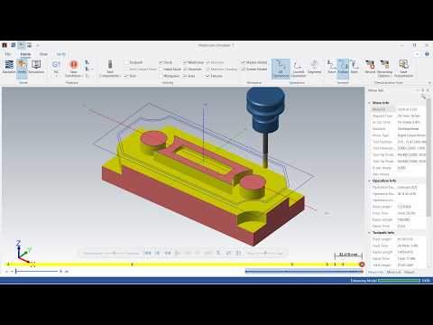
To truly grasp the capabilities of modern manufacturing software, studying real-world CNC CAD CAM examples is invaluable. For instance, when programming a standard pocket milling operation, Mastercam allows you to optimize high-speed toolpaths through Dynamic Motion. This reduces overall cycle times while extending cutting tool life dramatically.

Another common application involves complex 3D contouring. By selecting optimized surface finishing toolpaths, you can achieve superior surface quality while keeping setup times to a minimum. These practical workflow examples highlight how blending computer-aided design with automated toolpath generation eliminates manual programming errors and improves part consistency.

Best Tricks for Efficient CNC Milling

To maximize efficiency and accuracy in Mastercam 2027, keep these pro tips in mind during your programming setup:
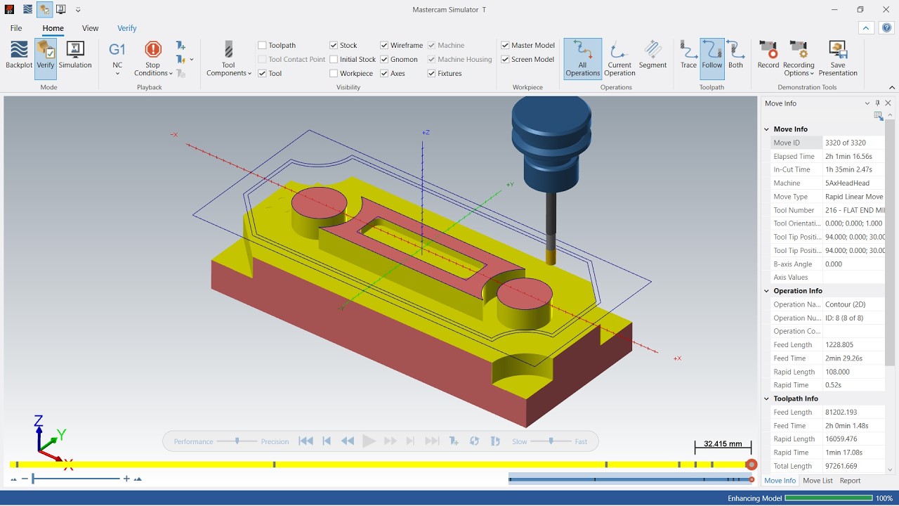
- Leverage Toolpath Verification: Always run 3D solid simulation and verification before sending G-code to the machine to prevent accidental crashes.
- Optimize Feed Rates: Use dynamic feeds to automatically adapt to varying material engagement, protecting your tools from sudden stress.
- Create Custom Tool Libraries: Save your frequently used end mills, drills, and feeds/speeds presets to accelerate future programming projects.

Conclusion

Mastering CNC milling requires a blend of hands-on mechanical knowledge and smart software utilization. By analyzing clear CNC CAD CAM examples and applying the right workflow tricks in Mastercam 2027, you can dramatically improve your machining speed, precision, and efficiency. Start practicing these steps today to elevate your CNC programming projects to the next level!


🎬 Related Video Reference

Mastering Mastercam Lathe: A Step-by-Step Guide to CNC Toolpath Generation

Mastercam remains one of the most powerful CAD/CAM software solutions for computer-aided manufacturing. Whether you are a beginner machinist or an experienced CNC programmer, understanding modern CNC toolpath generation is critical to optimizing cycle times, protecting cutting tools, and achieving precise turned components.

In this guide, we walk through the essential turning operations required to complete a comprehensive lathe workflow in Mastercam, covering everything from initial facing cuts to complex internal grooving.

Essential Mastercam Turning Operations

To build a robust lathe program, you must master the fundamental turning toolpaths provided by Mastercam:

  • Facing: The foundational step for any lathe setup. Facing establishes a clean reference surface at Z-zero, ensuring subsequent operations maintain tight dimensional accuracy.
  • OD Roughing and Finishing: Removing heavy material quickly requires efficient roughing strategies. Mastercam allows programmers to set aggressive cut depths for Outer Diameter (OD) roughing, followed by a high-speed finish pass to achieve excellent surface finishes.
  • Centerline Drilling: Setting up accurate drilling toolpaths prepares internal bores for subsequent operations like boring or grooving.
  • ID Grooving: Machining Internal Diameter (ID) grooves demands precision. Proper tool clearance and smooth lead-in/lead-out moves prevent tool breakage inside narrow bores.

Streamlining Code with the G71 Canned Cycle

Modern machining relies heavily on clean G-code output. Advanced CNC toolpath generation isn't just about moving the cutting tool—it is about writing manageable, optimized code.

By leveraging canned cycles like the G71 rough turning cycle, Mastercam compresses long toolpaths into compact code blocks. This drastically reduces the memory footprint on CNC machine controllers while making manual adjustments on the shop floor fast and efficient.

Final Thoughts

Mastering these core Mastercam operations grants programmers full control over their manufacturing workflow. By fine-tuning your cut parameters, stock allowances, and cycle settings, you can elevate your CNC toolpath generation skills and produce high-quality parts reliably every single time.

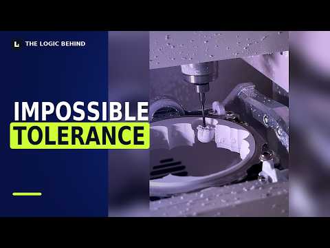
Mastering Titanium: A High-Precision CNC Machining Case Study

Titanium is celebrated across advanced industries for its incredible strength-to-weight ratio, extreme corrosion resistance, and biocompatibility. However, for manufacturing engineers, it presents one of the most formidable challenges on the shop floor. In this CNC machining case study, we take a deep dive into the complex engineering required to machine hardened titanium with extreme precision.

The Titanium Challenge: Why It’s Nearly Impossible

Why is titanium notoriously difficult to cut? Unlike standard materials such as aluminum or mild steel, titanium possesses exceptionally poor thermal conductivity. When cutting titanium, up to 80% of the heat generated during the process transfers directly into the cutting tool rather than dissipating through the removed chips.

This localized heat accumulation leads to rapid tool wear, thermal expansion, and potential deformation of the workpiece. Furthermore, titanium's elasticity causes "spring-back" effects, while its tendency to work-harden under strain makes clean cuts exceptionally hard to achieve without premature tool failure.

Thermal Management and Advanced Engineering Solutions

Overcoming these barriers requires a meticulous balance of advanced tooling, precise programming, and strict thermal control. As demonstrated in this CNC machining case study, modern high-precision setups rely on several critical techniques to achieve success:

  • High-Pressure Coolant Systems: Directing high-pressure coolant directly at the cutting zone rapidly strips away heat and prevents chip re-cutting.
  • Specialized Tool Geometries: Utilizing custom carbide cutters featuring advanced heat-resistant coatings (such as AlTiN) reduces friction and extends tool life.
  • Optimized Toolpaths: Implementing high-speed trochoidal milling strategies helps minimize continuous tool engagement, effectively controlling heat buildup.

Achieving Uncompromising Precision

Precision titanium components are non-negotiable in high-stakes sectors like aerospace engineering and medical device manufacturing, where micro-deviations can result in part failure. Through rigorous thermal management and optimized cutting parameters, engineers can achieve tight tolerances down to the micron level.

This detailed CNC machining case study proves that while titanium pushes cutting tools to their absolute limits, innovative engineering solutions make ultra-precise titanium fabrication both reliable and repeatable.

From Pattern to Cut: Applying CNC Machining Logic for Fast DXF Generation

cnc cadcam system
From Pattern to Cut: Applying CNC Machining Logic for Fast DXF Generation

From Pattern to Cut: Applying CNC Machining Logic for Fast DXF Generation

This article provides an in-depth exploration of CNC machining logic, covering foundational concepts, practical applications, and engineering insights.

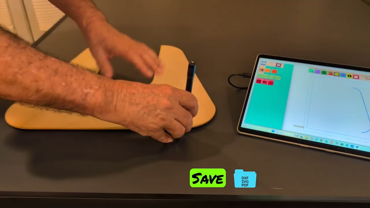
Have you ever found yourself working on a workshop project where you needed to duplicate a physical part, wood template, or custom pattern immediately? In custom fabrication and woodworking, manually measuring and drawing complex curves in CAD from scratch can be a major bottleneck. Fortunately, bridging the gap between physical objects and digital cutting tools is simple once you master the digitizing process.

Why Tracing Physical Patterns Saves Time

Creating a quick DXF file directly from a physical template allows fabricators to bypass tedious CAD modeling. Whether you are working with a paper template, a handmade wooden cutout, or an existing machine component, digitizing the outline provides an accurate 2D vector path ready for toolpath generation.

By capturing the exact geometry of your pattern, you eliminate guesswork and dramatically reduce turn-around time for custom jobs.

Applying Sound CNC Machining Logic to Digitization

To get high-quality results from a traced object, you must integrate fundamental CNC machining logic into your workflow. When converting a physical pattern into a vector file, you are doing more than capturing a visual shape—you are creating precise geometry that a cutting bit will execute.

Applying practical CNC machining logic means anticipating tool bit diameters, material kerf, lead-ins, and hold-down strategies during the initial vector cleanup stage. For example, if your traced wooden template features sharp inside corners, sound CNC machining logic reminds us that a rotating end mill cannot cut a zero-radius internal angle. Recognizing these real-world constraints early allows you to modify your DXF file—adding dogbone reliefs or adjusting radii—before sending the design to the machine.

Steps for Converting a Template into a Cut-Ready DXF

  1. Capture the Pattern: Place your template on a high-contrast background to get a clean, undistorted visual trace or scan.
  2. Vectorize and Clean: Import the image into your vector design software. Smooth out node clusters and jagged lines to ensure fluid machine motion.
  3. Scale and Verify: Measure critical reference points on the original physical template and scale your digital DXF file to ensure 1:1 accuracy.
  4. Export for CAM: Save your clean vector drawing as a DXF file, ready to be imported into your preferred CAM software for toolpathing.

By pairing fast pattern-tracing techniques with smart digital preparation, you can turn any physical template into a cut-ready DXF file in a matter of minutes.


🎬 Related Video Reference

11/05/2026

Mastercam Turning Tutorial: Practical CNC Programming Exercises for Stepped Shafts

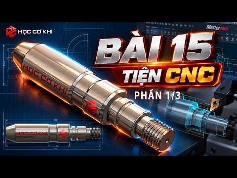
Mastering Mastercam requires more than just understanding theoretical concepts—it demands hands-on practice through real-world CNC programming exercises. In this step-by-step guide, we take a deep dive into CNC lathe programming, focusing on how to machine a complex stepped shaft featuring integrated external threads.

Why Stepped Shaft Threading Matters for CNC Machinists

One of the most effective CNC programming exercises for lathe operations is machining a stepped shaft with external threads. This specific geometry combines several fundamental turning operations into a single workflow, making it an essential training project for both beginner and intermediate CAD/CAM programmers.

By completing this tutorial, you will gain practical experience in: - Importing and setting up geometry correctly in Mastercam. - Defining stock dimensions and chuck jaw clamping locations. - Generating efficient roughing and finishing toolpaths for multi-diameter shafts. - Programming precise threading parameters for standard screw threads.

Step-by-Step CNC Turning Workflow in Mastercam

1. Geometry & Job Setup

Before applying toolpaths, define your machine definition (Lathe Default) and configure the stock parameters. Proper stock definition ensures accurate tool path generation and prevents collisions during machining simulation.

2. Outer Diameter (OD) Roughing & Finishing

To machine the steps along the shaft, apply a Facing path followed by an OD Roughing toolpath. Mastercam allows you to optimize cut depth, lead-in/lead-out vectors, and feed rates. Follow this up with an OD Finishing pass to achieve the required surface finish and tight dimensional tolerances.

3. Thread Cutting Operation

Threading requires specific tool geometry and parameter inputs, such as lead angle, thread pitch, and major/minor diameters. Utilizing Mastercam's Thread toolpath routine allows you to quickly set single-point threading passes with high accuracy.

Elevate Your CAM Skills with Practical Practice

Consistently practicing targeted CNC programming exercises is the key to building confidence in automated manufacturing. Verifying your toolpaths using Mastercam's 3D simulation tool allows you to visually inspect material removal, verify clearance angles, and eliminate potential G-code errors before sending the file to the CNC machine.

Whether you are preparing for a career in mechanical engineering or looking to refine your shop floor skills, mastering stepped shaft programming on Mastercam is a vital step toward professional success.

Stop Relying on Third Parties: Bring Ideas to Life with Real CNC Project Samples

Have you ever had a brilliant idea for a new product, only to see it stall because you had to rely on external manufacturers? Waiting for third-party suppliers, dealing with high minimum order quantities, and paying steep prototyping fees can quickly drain your momentum. It’s time to break free from those limitations and take full control of your creative process.

Why Bring Your Manufacturing In-House?

When you bring fabrication in-house using modern CNC (Computer Numerical Control) machines, you eliminate bottlenecks and gain complete design freedom. Whether you need to fabricate complex molds, develop physical prototypes, or scale your business up to small-batch production, CNC technology gives you the precision and power to do it on your own terms.

By analyzing diverse CNC project samples, you can see firsthand how easily raw materials like aluminum, wood, plastics, and composites can be transformed into finished, market-ready items.

Unlock Your Creative Potential

Taking your production to the next level begins with seeing what is truly possible. From custom injection molds to detailed mechanical parts, examining high-quality CNC project samples provides the blueprint and inspiration for your own product lines.

When you own your manufacturing setup, you can: - Iterate Faster: Test and refine your prototypes in hours instead of weeks. - Cut Costs: Eliminate middleman markups on low-volume production runs. - Protect Your IP: Keep your proprietary designs safely inside your workshop.

Take Your Production to the Next Level

Stop waiting for someone else to build your future. By incorporating CNC solutions into your workflow, you bridge the gap between digital design and physical reality. Studying proven CNC project samples shows that with the right equipment and mindset, turning your boldest ideas into tangible products isn't just possible—it's completely within your control.

Ready to transform your workflow? Take the leap today and start bringing your unique product ideas to life!

Mastering CNC Toolpath Theory: How to Eliminate Material Chip-Out for Clean Cuts

cnc cadcam system
Mastering CNC Toolpath Theory: How to Eliminate Material Chip-Out for Clean Cuts

Mastering CNC Toolpath Theory: How to Eliminate Material Chip-Out for Clean Cuts

This article provides an in-depth exploration of CNC toolpath theory, covering foundational concepts, practical applications, and engineering insights.

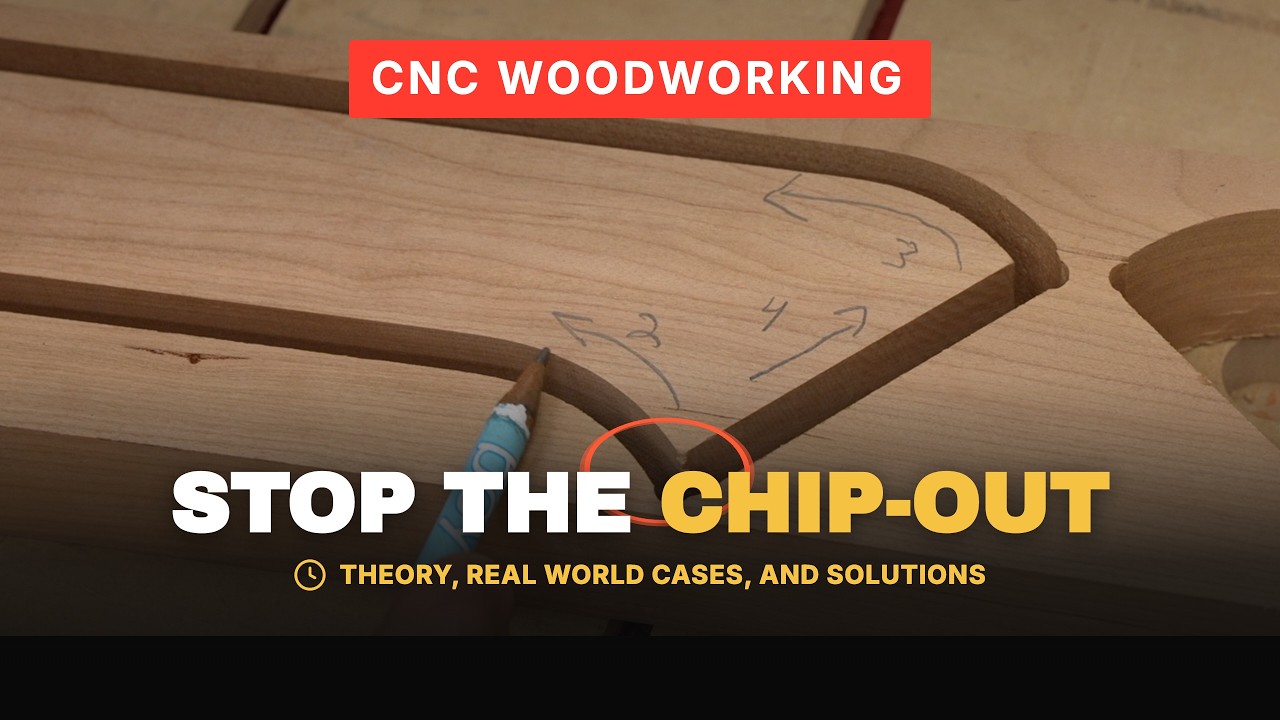
Nothing ruins an otherwise flawless CNC project faster than material chip-out. You spend hours designing your part, setting up your stock, and running a job, only to discover splintered edges or ugly tear-out during the final pass. While many makers blame low-quality lumber or dull end mills, the root cause usually comes down to how your CAM software generates cutting movements.

By understanding CNC toolpath theory, you can easily predict where cutting forces will cause blowout and adjust your strategies before wasting valuable stock.

Why Does CNC Chip-Out Happen?

Chip-out occurs when the cutting edge of a bit exits the workpiece material without sufficient support. As the flutes scoop out material, shear stress builds up along the cut line. If the surrounding grain or laminate isn't strong enough to resist that outward force, the material fractures—leaving ragged, ugly edges behind.

Factors like wood grain direction, feed rates, and tool geometry (upcut vs. downcut spiral bits) certainly impact edge quality. However, the direction of travel and how the cutter enters or exits the material play the most critical roles.

Applying CNC Toolpath Theory to Stop Tear-Out

When putting practical CNC toolpath theory into action, your primary objective is to direct cutting forces back into the stock rather than pulling them outward. Here are essential toolpath adjustments to implement in your CAM workflow:

  • Climb vs. Conventional Milling: Switching between climb and conventional cutting changes where the cutter tooth enters and exits the profile. Climb milling starts at maximum chip thickness and exits at zero thickness, which often prevents surface tear-out on sensitive hardwoods and laminates.
  • Lead-Ins and Lead-Outs: Instead of plunging directly onto a vector boundary or lifting straight up at a corner, use arc-shaped lead-in and lead-out moves. This gradual engagement prevents harsh force spikes that cause edge chipping.
  • Ramping Cuts: Ramping the bit into the material at a smooth angle rather than plunging straight down reduces vertical pressure, protecting delicate top veneers from lifting.

Smart Machining Strategies for Perfect Edges

Mastering CNC toolpath theory allows you to combine clever machining tactics for maximum cut quality. For challenging materials like veneered plywood, consider running a shallow scoring pass using a downcut bit first, followed by a full-depth pass. Alternatively, leave a thin "skin" of material during roughing and execute a light finishing pass to clean up the edge effortlessly.

By optimizing your toolpaths to handle material forces intelligently, you will eliminate costly re-dos, reduce hand sanding, and achieve professional, chip-free cuts on every single project.


🎬 Related Video Reference

11/04/2026

Mastering Mastercam: Practical CNC CAD CAM Examples for Efficient Milling

Computer-Aided Design (CAD) and Computer-Aided Manufacturing (CAM) have completely revolutionized modern component manufacturing. For machinists and programmers using advanced software like Mastercam, mastering toolpath strategies and software tricks is essential for achieving high precision and reducing machine downtime. Whether you are a beginner or looking to refine your programming workflow, exploring real-world CNC CAD CAM examples can significantly speed up your learning curve.

In this guide, we will break down essential steps and smart tricks in Mastercam to help you elevate your CNC milling efficiency and part quality.

Streamlining Your Setup Workflow

Before diving into toolpath generation, establishing a clean design environment is critical. Mastercam enables users to import complex 3D models or quickly sketch 2D geometry. The key to successful machining lies in disciplined stock setup, accurate origin positioning, and proper tool selection.

When analyzing functional CNC CAD CAM examples, you quickly realize that setting accurate program zero points and defining clear work coordinate systems (WCS) prevents costly tool collisions and material waste.

Essential Mastercam Tricks for Faster Milling

To maximize tool life and drastically reduce cycle times, keep these practical techniques in mind:

  • Leverage Dynamic Motion: Traditional toolpaths often cause excessive tool wear due to full-width engagement. Utilizing Dynamic Motion technology maintains a constant chip load, allowing for higher cutting speeds and deeper axial passes.
  • Optimize Step-Over Distances: Adjusting step-over percentages according to your end mill diameter ensures smooth surface finishes without overloading the machine spindle.
  • Run Full 3D Verification: Never send raw code directly to the machine control. Always run stock simulations in Mastercam to verify tool movements, check fixture clearances, and eliminate gouging risks.

Achieving Superior Part Precision

Studying practical CNC CAD CAM examples demonstrates how subtle tweaks in lead-in/lead-out vectors, ramp angles, and feed rate adjustments yield dramatic improvements on the shop floor. By combining smart geometry preparation with optimized machining toolpaths, you can transition from simple tutorial parts to complex manufacturing projects with complete confidence.

Start applying these Mastercam strategies today to refine your CAD/CAM process and achieve flawless CNC milling results!

Mastering Versatile Materials: How Smart CNC Machining Logic Makes Cutting Cork Easy

When most people think of computer numerical control (CNC) technology, heavy metals like aluminum or dense hardwoods usually come to mind. However, modern automated cutting tools are far more versatile than you might expect. From delicate plastics and dense composites to soft, organic substrates, almost any material can be processed with total precision. Understanding the underlying CNC machining logic allows operators to seamlessly adapt their workflows to handle unconventional materials—even cork.

Unlocking Material Versatility: From Hard Metals to Soft Cork

Cutting soft or fibrous materials like cork presents unique challenges. Unlike rigid metals, flexible substrates require carefully considered feed rates, specialized tool choices, and proper holding methods to prevent tearing or frayed edges. However, once your speeds and toolpaths are correctly calculated, modern equipment handles cork with surprising ease. Whether you are fabricating custom industrial gaskets, floor underlayments, or decorative wall tiles, expanding your material repertoire opens up exciting new possibilities for your shop.

Streamlining Workflow with Advanced Tracing Tools

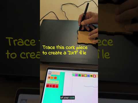
One of the biggest hurdles in working with custom or non-standard parts is converting physical templates into clean, cut-ready vector files. This is where modern digitizing solutions, such as The Logic Trace board, become invaluable. By placing a physical cork component directly onto the tracing board and tracing its outline, you can instantly generate a precise vector file ready for production.

Integrating efficient CNC machining logic into your digital prep stage removes the tedious guesswork. Instead of spending hours manually measuring and re-drawing irregular outlines in CAD software, digital tracing tools immediately translate physical shapes into precise digital geometry. This seamless transition from physical pattern to G-code ensures exact fitment while significantly cutting down project lead times.

Maximize Your Workshop Potential

Unlocking the full capabilities of your cutting equipment comes down to combining versatile hardware with intuitive software solutions. Adopting smart CNC machining logic alongside rapid digitizing technology enables your workshop to take on diverse, non-traditional projects with complete confidence—no matter what material comes through your door.

Demystifying CNC Working Concepts: Routers, Toolpaths, and Software Explained

cnc cadcam system
Demystifying CNC Working Concepts: Routers, Toolpaths, and Software Explained

Demystifying CNC Working Concepts: Routers, Toolpaths, and Software Explained

This article provides an in-depth exploration of CNC working concepts, covering foundational concepts, practical applications, and engineering insights.

Stepping into the world of computer-controlled woodworking can feel overwhelming with all the technical jargon thrown around. However, understanding the core CNC working concepts isn't as complex as it seems. Whether you are a hobbyist looking to create intricate crafts or a professional scaling up production, grasping how hardware, software, and tooling collaborate is the key to mastering CNC routing.

The Trio: Hardware, Software, and Toolpaths

At its heart, CNC machining relies on a seamless workflow driven by three main components: CAD/CAM software, toolpaths, and the physical CNC router.

  1. CAD/CAM Software: CAD (Computer-Aided Design) is where your design begins visually. Once your vector or 3D model is ready, CAM (Computer-Aided Manufacturing) software translates that visual design into G-code—the numeric language the machine understands.
  2. Toolpaths: A toolpath defines the precise trajectory the router bit will take. It controls parameters like cut depth, stepover, feed rate, and movement direction, ensuring accurate profiling, pocketing, and carving.
  3. The CNC Router: The physical machine executes these digital instructions, moving precisely along the X, Y, and Z axes to shape your workpiece.

Selecting the Right Tooling and Materials

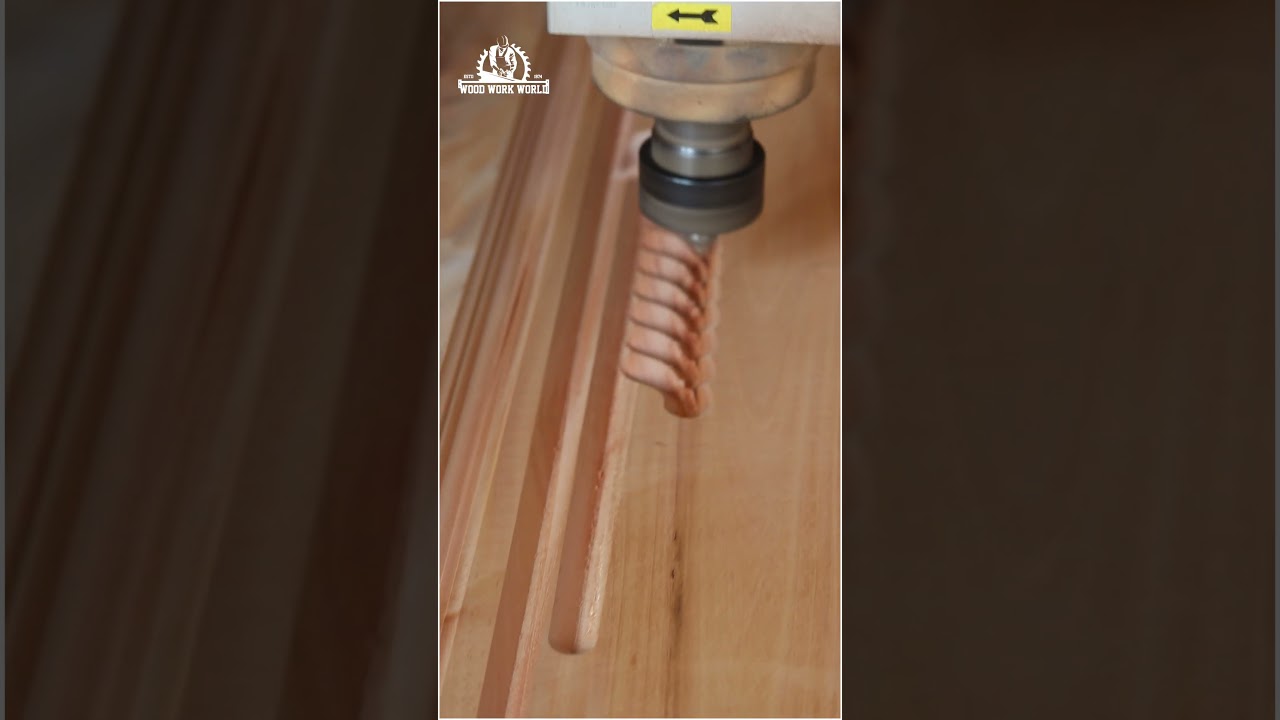
A crucial part of practical CNC working concepts involves choosing the right bit for your specific material. Different projects require specialized router bits—such as down-cut bits for clean top edges, up-cut bits for efficient chip evacuation, or compression bits for double-sided veneers.

Pairing your bit selection with proper feeds and speeds (how fast the bit spins versus how fast the machine moves through the material) prevents material burning, minimizes tool wear, and ensures clean, smooth cuts every time.

Bringing Your Vision to Life

By breaking down these foundational CNC working concepts, you bridge the gap between digital design and physical reality. Once you understand how CAD software translates creative ideas into actionable toolpaths, operating a CNC router becomes an intuitive and highly rewarding craft. Equip yourself with a quality starter bit set, practice machine setup techniques, and take your woodworking projects to the next level!


🎬 Related Video Reference

11/03/2026

Understanding CNC Toolpath Theory: A Complete Guide to Toolpath Simulation

Computer Numerical Control (CNC) machining relies heavily on accuracy, precision, and efficiency. Before sending a file to your router or milling machine, visualizing how the cutting tool moves across the raw material is a vital step. Understanding fundamental CNC toolpath theory is essential for creating error-free designs and preventing costly machine collisions.

In software like ArtCAM, toolpath simulation allows digital creators and machinists to preview the entire cutting process in a virtual environment. Here is what you need to know about toolpath simulation and how it transforms theoretical concepts into physical reality.

Why Toolpath Simulation is Crucial

Toolpath simulation acts as your safety net. Machining mistakes—such as setting an incorrect plunge rate, picking the wrong bit, or failing to clear stock material—can lead to broken tools or damaged workpieces.

By applying practical CNC toolpath theory, you can evaluate how vector geometry translates into physical tool movements. A 3D preview shows you exact material removal, surface finish quality, and potential interference zones, saving both time and material costs.

How to Simulate Toolpaths Step-by-Step

  1. Vector Preparation: Ensure all vectors in your design software are clean, joined, and properly positioned within the material boundaries.
  2. Tool Selection and Strategy: Choose the correct cutting bit (such as an end mill, ball nose, or V-bit) based on your design requirements.
  3. Toolpath Generation: Calculate profile, pocket, or 3D relief toolpaths according to your chosen depth and stepover settings.
  4. Run the 3D Simulation: Execute the simulation feature in ArtCAM or your preferred CAM software. Watch the virtual bit cut away material in real time to verify the final geometry.

Key Benefits of Virtual Verification

  • Collision Avoidance: Catch rapid movement errors or improper clearance heights before physically powering up your CNC router.
  • Time Optimization: Estimate accurate machining times and refine feeds and speeds for maximum efficiency.
  • Quality Assurance: Inspect the final rendered model to confirm that fine details and sharp corners are preserved.

Mastering CNC toolpath theory through software simulation empowers operators of all skill levels to produce precise, high-quality finished products with complete confidence. Always simulate your toolpaths before cutting to ensure a smooth, successful manufacturing workflow.

Demystifying Modern Manufacturing: A Guide to CNC CAD CAM Principles

cnc cadcam system
Demystifying Modern Manufacturing: A Guide to CNC CAD CAM Principles

Demystifying Modern Manufacturing: A Guide to CNC CAD CAM Principles

This article provides an in-depth exploration of CNC CAD CAM principles, covering foundational concepts, practical applications, and engineering insights.

In today’s fast-paced industrial world, Computer Numerical Control (CNC) technology has completely revolutionized how we design and fabricate complex components. From high-precision aerospace parts to custom automotive components, automated machining is the backbone of modern production. But how exactly do these sophisticated machines turn a simple digital concept into a tangible, physical object? It all comes down to fundamental CNC CAD CAM principles that bridge creative engineering with mechanical execution.

The Digital Workflow: Understanding CAD and CAM

At the heart of every CNC operation is a seamless digital translation process divided into two main stages:

  1. CAD (Computer-Aided Design): This is where the magic begins. Engineers and designers use CAD software to create precise 2D vector drawings or 3D solid models of the desired part. This digital blueprint defines the exact geometry, dimensions, and tolerances.
  2. CAM (Computer-Aided Manufacturing): Once the design is finalized, CAM software takes over. It analyzes the CAD model to calculate the most efficient cutting strategies, tool paths, speeds, and feeds.

The CAM software then converts the digital model into machine-readable instructions, predominantly written in G-code and M-code. Mastering these basic CNC CAD CAM principles enables manufacturers to significantly optimize production speed, reduce material waste, and extend tool life.

How the CNC Machine Executes the Code

Once the CNC controller receives the generated program, it acts as the digital "brain" of the physical machine. It sends micro-electric signals to drive motors across multiple axes—typically X, Y, and Z axes on standard mills, or X and Z on lathes.

As the cutting tool or workpiece moves along the calculated paths, high-speed spindles spin tools to shear away excess material. Advanced closed-loop feedback systems constantly monitor positional data, ensuring that every cut aligns perfectly with the original design specs down to a fraction of a millimeter.

Why Mastering CNC Principles Matters

Whether you are a student, hobbyist, or industry professional, grasping core CNC CAD CAM principles is essential for navigating today’s automated manufacturing landscape. By combining intuitive digital design with computerized mechanical precision, CNC technology allows us to create complex parts with unmatched accuracy, flawless repeatability, and unprecedented efficiency.


🎬 Related Video Reference

Mastering the Basics: A Guide to Essential CNC Working Concepts (Part 1)

Computer Numerical Control (CNC) machining has revolutionized modern woodworking, digital fabrication, and prototyping. Whether you are a passionate DIY hobbyist or looking to step into automated manufacturing, understanding essential CNC working concepts is the critical first step toward achieving precise and successful projects.

In this beginner-friendly guide, we explore the fundamental mechanics and workflow required to set up and run your first CNC machine effectively.

What is CNC Machining?

At its core, a CNC machine converts digital designs into physical objects by using computer software to direct motorized cutting tools. Unlike manual routing or carving, CNC operations rely on precise numerical control across multiple axes—typically X (left to right), Y (front to back), and Z (up and down).

The entire workflow follows a simple pipeline: 1. CAD (Computer-Aided Design): You create a 2D or 3D digital model of your design. 2. CAM (Computer-Aided Manufacturing): You define toolpaths, cut depths, and bit sizes. 3. G-Code Generation: The software translates the toolpath into G-code, the precise language your machine reads to execute the physical movement.

Essential CNC Working Concepts for Beginners

To achieve clean cuts and avoid costly mistakes, mastering these core CNC working concepts will save you countless hours of troubleshooting:

  • Workpiece Securing: Ensuring your material is firmly clamped, screwed down, or vacuum-sealed to the spoilerboard prevents shifting during high-speed cutting.
  • Machine Zero vs. Work Zero: Machine zero is the fixed home position of the router, while work zero (X=0, Y=0, Z=0) is the specific starting reference point set on your stock material.
  • Feeds and Speeds: Balancing spindle speed (rotational speed in RPM) with feed rate (how fast the tool moves through material) dictates cut quality, chip clearance, and bit lifespan.
  • Bit Selection: Selecting the right end mill—such as an up-cut, down-cut, or compression bit—depends on your material and desired surface finish.

Setting Up Your First Cut

Before sending G-code to your machine, always perform a safety check. Ensure your material is locked down, your bit is tightened in the collet, and your Z-probe accurately zeros the height of your cutter relative to the stock surface.

Conclusion

Taking the time to learn these foundational CNC working concepts gives you the confidence to turn raw stock into intricate, high-quality finished pieces. Stay tuned for Part 2 of our comprehensive tutorial series, where we will dive deeper into software toolpaths, speed optimization, and post-processing techniques!

Optimizing Toolpaths: How Operation Order Refines Your CNC CAD CAM Principles

When setting up a new project in FreeCAD CAM, generating toolpaths is only half the battle. To achieve professional-grade results, you must understand how operation sequencing impacts the overall machining process. Applying sound CNC CAD CAM principles ensures that your toolpaths are not only efficient but also safe for both your workpiece and cutting tools.

Why Operation Sequencing Matters in FreeCAD CAM

In computer-aided manufacturing, the default order of operations generated by your software might not always be the most logical choice. Reordering your CNC operations allows you to maintain part rigidity, prevent burrs, and eliminate unnecessary rapid movements.

For instance, clearing out inner pockets before cutting the outer profile keeps the stock securely anchored to the machine bed for as long as possible. Ignoring these foundational CNC CAD CAM principles can result in stock chatter, broken bits, or inaccurate final dimensions.

How to Reorder Operations for Smarter Toolpaths

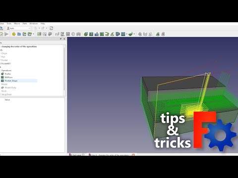
FreeCAD CAM makes adjusting your workflow simple and intuitive. By navigating the Job Tree, you can easily drag and drop operations or use sequence controls to reorder your cuts.

Here are a few practical rules of thumb to optimize your setup:

  • Roughing First, Finishing Second: Always remove bulk material with heavier roughing passes before performing delicate finishing passes.
  • Inside to Outside: Drill holes and clear interior features prior to severing the outer perimeter of your part.
  • Minimize Tool Changes: Group operations that use the same end mill together to reduce overall cycle time.

Elevating Your Workflow for Cleaner Cuts

By taking control of your operation sequence, you transform chaotic toolpaths into streamlined, high-precision strategies. Integrating core CNC CAD CAM principles into your daily FreeCAD routine will consistently deliver smoother surface finishes, longer tool life, and significantly faster production times. Experiment with reordering your operations on your next job and see the difference in your final cuts!

11/02/2026

Mastering VMC Cutting Tools: A Beginner’s CNC Operation Manual Guide

Whether you are a beginner studying your first CNC operation manual or an experienced operator looking to refresh your knowledge, understanding the right tools for Vertical Machining Centers (VMC) is crucial. In CNC milling, selecting the proper tooling directly affects machining accuracy, surface finish, and overall production efficiency.

Here is a breakdown of the essential cutting tools used in VMC and CNC milling machines and how to choose the right ones for your projects.

Common Types of CNC Milling Machine Tools

  1. End Mills End mills are the most versatile cutting tools in CNC milling. Unlike standard drill bits, end mills can cut horizontally, vertically, and sideways.
  2. Flat End Mills: Ideal for general milling, pocketing, and producing flat surfaces.
  3. Ball Nose End Mills: Best suited for 3D contouring, smooth surfaces, and complex curved geometries.
  4. Bull Nose End Mills: Feature a flat bottom with rounded corners, making them durable for heavy roughing and corner radii.

  5. Face Mills Face mills are designed to remove large amounts of material across wide surface areas. They feature replaceable carbide inserts around their outer edge, allowing machinists to flatten stock quickly and cost-effectively.

  6. Drills and Taps

  7. Spotting Drills: Used to create precise starting points for deep drilling.
  8. Twist Drills: The standard tool for drilling round holes into raw stock.
  9. Taps: Used after drilling to cut internal threads for screws and bolts.

Why Matching Tools to Machine Specs Matters

Every milling operation requires specific cutting speeds, feed rates, and tool setups. Before setting up your machine or assigning tool offsets, you should always cross-reference tool parameters with your standard CNC operation manual to maintain efficiency and avoid spindle overload. Proper tool length measurement and diameter offsets are critical to preventing costly collisions during high-speed VMC operations.

Final Thoughts

Understanding the functional differences between end mills, face mills, and drilling tools is the foundation of successful CNC machining. By combining proper tool selection with the safety guidelines found in your CNC operation manual, you can maximize tool life, enhance workpiece precision, and boost overall productivity on the shop floor.

11/01/2026

How to Operate a CNC Turning Machine: The Essential CNC Handbook for Beginners

Stepping into the world of modern manufacturing can feel overwhelming, but mastering computer-controlled machinery opens up incredible career opportunities. If you are eager to learn about automated turning operations, this essential CNC handbook for beginners will guide you through the core fundamentals of operating a CNC turning machine safely and efficiently.

What is a CNC Turning Machine?

A CNC (Computer Numerical Control) turning machine, commonly known as a CNC lathe, holds a cylindrical workpiece in a rotating chuck while feeding cutting tools against it to shape metal, plastic, or wood. Unlike traditional manual lathes, CNC machines use pre-programmed software instructions (G-code and M-code) to execute complex cuts with extreme accuracy and repeatability.

Key Steps to Operate a CNC Turning Machine

Operating a CNC turning machine requires systematic preparation, proper machine setup, and strict adherence to safety protocols. Here is a step-by-step breakdown:

  1. Prioritize Safety: Before touching the machine, wear proper Personal Protective Equipment (PPE), including safety glasses and steel-toe boots. Never wear loose clothing or jewelry around rotating spindles.
  2. Setup the Workpiece: Securely mount your raw material into the lathe chuck. Proper clamping force is vital to prevent material from shifting during high-speed rotation.
  3. Load the CNC Program: Input or transfer the G-code program into the machine’s control panel. This code instructs the lathe on spindle speeds, tool movements, and coolant delivery.
  4. Set Tool Offsets and Work Coordinates: Load the required cutting tools into the turret. Accurately set tool geometry offsets and establish your work zero position ($X$ and $Z$ axes).
  5. Perform a Dry Run: Run the program in the air above the part without cutting material. This safety check ensures tool paths are clear and prevents severe machine collisions.
  6. Execute and Monitor: Once verified, begin the machining process. Stay near the control panel and keep your hand near the emergency stop button during the first pass.

Essential Tips for Success

Treating your early projects as a practical CNC handbook for beginners will help you establish good shop habits. Always monitor cutting sounds and vibration during operation—unusual chatter often signals incorrect feed rates or worn tools. Furthermore, taking time to learn basic G-code editing directly on the controller will make troubleshooting much easier.

Conclusion

Learning to operate a CNC turning machine merges mechanical craft with digital software precision. By referring to a dependable CNC handbook for beginners and practicing consistent setup procedures, you can rapidly build confidence on the shop floor. Focus on safety, double-check your coordinates, and keep building your machining skills!

Mastering Fusion 360: The Ultimate CNC CAD CAM Introduction for Beginners

Getting started with digital fabrication can feel overwhelming, but mastering your machine's workflow is easier than you think. If you are looking for a complete CNC CAD CAM introduction, learning how to bridge the gap between 3D design and physical cutting is the most crucial step. Autodesk Fusion 360 has become the go-to software for makers, woodworkers, and engineers because it seamlessly combines Computer-Aided Design (CAD) and Computer-Aided Manufacturing (CAM) into a single, intuitive platform.

Why Integrated CAD/CAM Matters

In traditional manufacturing workflows, you would design a part in one application and then export it to a separate program to generate toolpaths. Fusion 360 eliminates this friction. By offering an integrated environment, any dimensional changes you make to your 3D CAD model automatically update your machining operations. This practical CNC CAD CAM introduction focuses on leveraging that unified system to save project setup time and prevent costly material waste.

Master the CAM Setup in 4 Simple Steps

To turn your digital 3D models into precise physical cuts, you need to understand the fundamental steps of the Fusion 360 Manufacture workspace:

  1. Define Your Setup and Work Coordinate System (WCS): Establish your stock material dimensions and set the origin (X, Y, and Z zero points). Accurately setting the WCS ensures your router bit begins cutting in the exact right spot on your workpiece.
  2. Select the Right Cutting Tools: Utilize Fusion 360’s extensive tool library to input parameters for your specific router bits. Matching your end mills, v-carve tools, or drill bits to your material—whether working with hardwood, MDF, or aluminum—is essential for clean cuts.
  3. Generate Precision Toolpaths: Choose the best cutting strategy for your geometry, such as 2D Contour for cutouts, 2D Pocket for clearing material, or Adaptive Clearing for efficient high-speed roughing.
  4. Simulate and Post-Process: Always run a toolpath simulation before sending files to your CNC router. Software simulations help you detect potential collisions, incorrect feed rates, or unintended stock gouges. Once verified, export your g-code using the correct post-processor for your machine.

Start Cutting with Confidence

Whether you are making custom furniture, crafting intricate signs, or prototyping mechanical components, this CNC CAD CAM introduction gives you the foundational knowledge to succeed. By taking the time to master stock setups, tool selection, and toolpath simulation in Fusion 360, you can move from digital concept to finished physical project quickly, safely, and accurately.

10/31/2026

Mastering External Machining: A Comprehensive CNC Software Guide to Tooling and Toolpaths

External machining on CNC machines is a cornerstone of modern precision manufacturing. Whether you are creating smooth cylindrical surfaces, intricate outer contours, precise chamfers, or clean steps, selecting the right physical cutting tools and pairing them with smart programming strategies is essential. To achieve top-tier surface finishes and maximum efficiency, following a reliable CNC software guide will help you bridge the gap between cutting-edge software and physical tooling.

Understanding External Machining Tools

External machining relies heavily on turning tools, inserts, and specialized milling cutters designed to shape the outer perimeter of a workpiece. Turning inserts—ranging from roughing and finishing bits to grooving and threading tools—must be selected based on material hardness, desired feed rates, and part geometry. Similarly, end mills and chamfer tools are frequently deployed for outer contouring and edge breaking on multi-axis CNC lathes and mills. Choosing the correct tool geometry and insert coating minimizes vibration, reduces heat buildup, and extends tool life significantly.

Optimizing Toolpaths with Software Precision

While high-quality physical tools do the actual cutting, advanced Computer-Aided Manufacturing (CAM) systems drive the machine's movement. A complete CNC software guide serves as a roadmap for setting ideal cutting parameters, tool speeds, and feed rates. Modern software enables programmers to create adaptive roughing strategies, smooth lead-ins, and accurate contouring paths that prevent tool overloading. By referencing a detailed CNC software guide, machinists can run digital simulations to detect potential collisions and optimize cycle times before a single chip is cut.

Conclusion: Balancing Tooling and Tech

Mastering external CNC machining requires harmony between hardware and software. By pairing high-performance turning inserts and milling cutters with optimized programming routines, manufacturers can dramatically increase throughput while maintaining strict tolerances. Keep your software tool libraries updated to match your physical tooling, and always verify toolpaths prior to production.

Master CNC Machining: Your Ultimate CNC Operation Manual for Turning, Facing, and Grooving

cnc cadcam system
Master CNC Machining: Your Ultimate CNC Operation Manual for Turning, Facing, and Grooving

Master CNC Machining: Your Ultimate CNC Operation Manual for Turning, Facing, and Grooving

This article provides an in-depth exploration of CNC operation manual, covering foundational concepts, practical applications, and engineering insights.

Computer Numerical Control (CNC) machining has revolutionized modern manufacturing, enabling operators to produce complex metal components with incredible accuracy. Whether you are a student starting out in industrial automation or an experienced machinist refining your craft, mastering foundational lathe operations is crucial. Think of this guide as your practical CNC operation manual for understanding three core processes: turning, facing, and grooving.

Understanding Essential Lathe Operations

Before writing code, an operator must understand what happens at the spindle. Every precision component relies on these fundamental procedures:

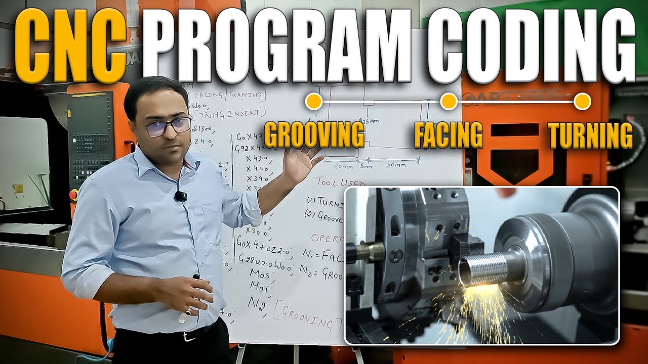
  • Facing: This initial operation cuts across the end of the workpiece to create a flat, smooth surface perpendicular to the rotational axis. It establishes an accurate starting point and ensures precise overall part length.
  • Turning: The primary method for reducing the outer diameter of a cylindrical material. By guiding the cutting tool along the length of the workpiece, you achieve precise dimensions and contours.
  • Grooving: This process cuts narrow channels or recesses into the workpiece. Grooving is essential for creating seats for O-rings, snap rings, or preparing a workpiece for cut-off.

Translating Operations into Precise CNC Code

Executing these movements flawlessly requires structured programming. A comprehensive CNC operation manual provides crucial reference points for selecting G-codes, M-codes, spindle speeds, tool offsets, and feed rates.

When setting up your program, pay close attention to:
1. Proper zero-point setup and tool path planning.
2. Depth of cut to prevent tool chatter or breakage.
3. Coolant control to manage heat during high-speed cutting.

Correct programming structure guarantees high surface quality while extending tool life and avoiding machine collisions.

Elevating Your Career with Practical Training

While reading theoretical guides is beneficial, hands-on shop-floor experience is what builds real expertise. Premier institutes, such as New RVM CAD Pune, lead the way in CAD design, CNC, and VMC practical training. Immersing yourself in modern machine environments allows you to bridge the gap between code on paper and finished metal parts.

Final Thoughts

Mastering lathe programming requires patience, precision, and continuous practice. Always keep a trusted CNC operation manual by your side for quick reference, focus on safety standards, and seek out quality skill development programs to supercharge your career in modern manufacturing.


🎬 Related Video Reference