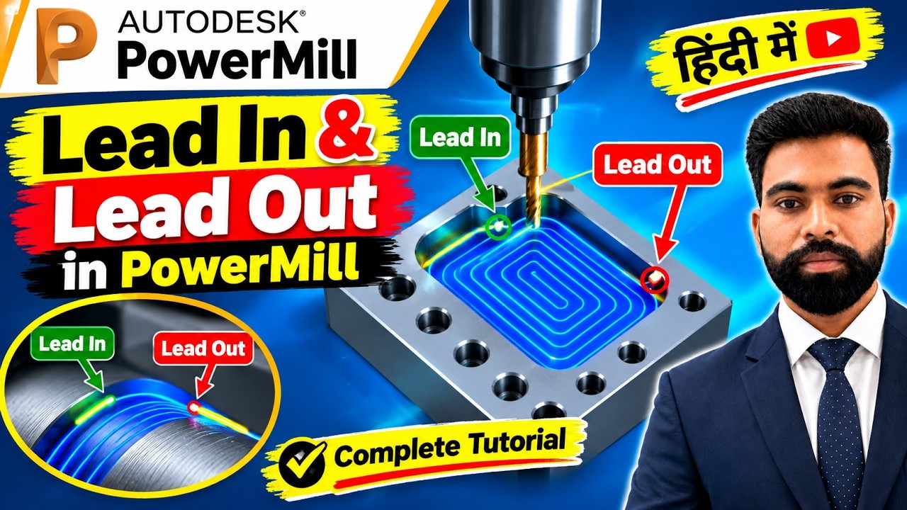
Mastering PowerMill: A Complete Guide to Lead In, Lead Out, and Toolpath Connections
This article provides an in-depth exploration of Toolpath, covering foundational concepts, practical applications, and engineering insights.
In the world of CNC programming and CAM software, achieving a perfect surface finish depends on more than just the cutting speed. One of the most critical aspects of professional machining is how the tool enters and exits the material. In PowerMill, these movements are controlled through "Leads and Links" settings. Understanding how to configure these is essential for anyone looking to create a high-quality toolpath that is both efficient and safe.
What are Lead In and Lead Out Settings?
Lead In and Lead Out settings define the movement of the cutting tool as it approaches the stock and as it leaves the finished surface.
* Lead In: This is the trajectory the tool takes to start cutting. Instead of plunging directly into the metal, which can damage the tool or the part, you can set an "Arc," "Surface Normal," or "Ramp" entry.
* Lead Out: This is the movement the tool makes after completing a pass. A smooth Lead Out prevents "witness marks" or burrs on the workpiece.
By mastering these settings, you ensure that the tool makes contact with the material gradually, reducing vibration and extending tool life.
Understanding Links and Connections
While Leads handle the entry and exit, "Links" manage the movements between segments of the cut. When a machine finishes one pass and needs to move to the next, the software must decide the safest and fastest way to get there. Whether the tool moves at a "Skim" height, an "Incremental" distance, or stays "On Surface," optimizing your toolpath connections ensures smoother transitions and significantly reduces air-cutting time.
Why Optimization Matters
Incorrect Lead In or Lead Out settings can lead to several issues, including tool breakage, poor surface quality, or even machine crashes. When you refine these connections, you aren't just making a program; you are optimizing the entire manufacturing process.
A well-configured toolpath results in:
1. Enhanced Surface Finish: Eliminates entry and exit marks on the final part.
2. Reduced Tool Wear: Protects the cutting edge from sudden impact.
3. Faster Cycle Times: Minimizes unnecessary retractions to the home position.
Whether you are working on complex 3D molds or simple 2D parts, taking the time to understand PowerMill’s Leads and Links will elevate your CAM programming from basic to expert level. By focusing on how the tool connects between cuts, you ensure a professional result every time.

No comments:
Post a Comment