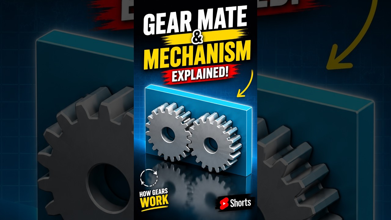
SolidWorks Gear Mate Explained: Elevate Your CAD/CAM Design Skills
This article provides an in-depth exploration of CAD/CAM, covering foundational concepts, practical applications, and engineering insights.
Gears are the backbone of mechanical engineering, playing a critical role in transferring rotational motion, adjusting torque, and controlling speed in complex machinery. When designing these mechanical systems digitally, engineers rely on advanced CAD/CAM software like SolidWorks to simulate real-world motion accurately.
One of the most essential tools for simulating realistic mechanical motion in 3D design is the SolidWorks Gear Mate. But how exactly does this feature work, and why is it so vital for mechanical designers? Let's break down the mechanics behind gear interactions and motion transfer.
Understanding the SolidWorks Gear Mate
In 3D assembly modeling, standard mates constrain components by keeping surfaces, edges, or axes aligned. However, mechanical mates—such as the Gear Mate—take design a step further by establishing a dynamic, proportional relationship between rotating parts.
When you apply a Gear Mate, you define a relative rotational ratio between two components (often based on pitch diameter or tooth count). As one gear rotates, the mate forces the adjacent gear to rotate proportionally in either the same or opposite direction. This simulates realistic gear teeth engagement without requiring the heavy computational power needed for real-time physical contact simulations.
How Gear Mechanisms Transfer Motion
The fundamental purpose of any gear mechanism is motion and power transmission. By varying the size and tooth arrangement of interacting gears, designers can precisely manage mechanical outputs:
- Torque and Speed Control: Driving a larger gear with a smaller gear (gear reduction) decreases output speed while multiplying torque.
- Directional Changes: Standard spur gear pairs reverse the direction of rotation, while bevel gears allow power transmission across angled axes.
- Synchronized Timing: Interlocked gear trains ensure exact timing and positioning across interconnected mechanical components.
Optimizing Mechanical Design in CAD/CAM Workflows
Accurately simulating gear interaction early in the digital design stage helps eliminate clearance issues, improper gear ratios, and spatial constraints long before physical prototypes are manufactured. Incorporating precise mechanical mates into your CAD/CAM projects ensures that your concepts translate seamlessly into functional, production-ready machinery.
Whether you are designing intricate gearboxes, automotive differentials, or industrial automation systems, mastering features like SolidWorks Gear Mate is an indispensable skill for modern engineers and 3D modeling professionals.
Visual Insights & Illustrations


No comments:
Post a Comment