Essential SolidWorks Exercise for Beginners: Boosting Your CAD/CAM Skills
This article provides an in-depth exploration of CAD/CAM, covering foundational concepts, practical applications, and engineering insights.
Whether you are a student starting your journey in mechanical engineering or a beginner looking to sharpen your parametric modeling techniques, practicing hands-on 3D exercises is essential. SolidWorks remains one of the premier software packages used across various engineering disciplines. Building a strong foundation in basic sketching and feature modeling is crucial for preparing yourself for complex CAD/CAM projects in modern manufacturing.
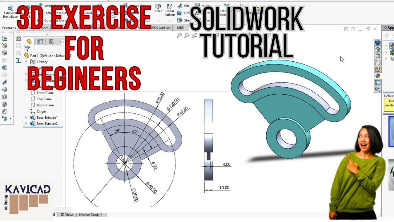
In this beginner-friendly tutorial guide, we break down the key steps to take a simple 2D mechanical drawing—featuring a curved arc profile—and translate it into an accurate 3D model.
Step 1: Analyzing the Technical Drawing
Before creating any features in SolidWorks, every designer must carefully interpret the reference drawing. Pay close attention to primary projection views, specifically the Front View. In this exercise, the component features a prominent arc-shaped geometry that forms the primary structure. Understanding how key dimensions relate between views helps prevent errors in your feature tree and ensures smooth design intent.
Step 2: Sketching and Applying Geometric Relations
Once you have analyzed the dimensions, open a new part file in SolidWorks and begin sketching:
- Select the Sketch Plane: Choose the Front Plane to match the orientation of the reference drawing view.
- Draft the Primary Geometry: Use the Arc tool (such as a 3-Point Arc or Centerpoint Arc) along with Line tools to outline the main profile.
- Add Constraints and Dimensions: Apply geometric relations like tangency, symmetry, and concentricity. Use the Smart Dimension tool to lock in precise measurements until the sketch is fully defined.
Maintaining fully defined sketches is a critical best practice in professional CAD/CAM environments to ensure model stability during future revisions.
Step 3: Generating the 3D Feature
With your 2D contour fully defined, switch to the Features tab and select Extruded Boss/Base. Enter the thickness value specified in the drawing to give your sketch 3D depth. If your part requires additional details like holes, fillets, or chamfers, create subsequent sketches on the model faces and utilize tools such as Extruded Cut.
Accelerate Your Mechanical Engineering Skills
Bridging the gap between theoretical knowledge and practical 3D design requires continuous practice. By regularly completing structured beginner exercises like this one, you build the technical intuition needed to thrive in modern CAD/CAM workflows. Pick up your dimensions, launch SolidWorks, and start modeling today!
Visual Insights & Illustrations


No comments:
Post a Comment